Shopping Cart
0 item(s) - USD 0.00- 5W Resistor (6)
- Arduino Development (66)
- Audio (8)
- Batteries (17)
- Cable & Wire (36)
- Capacitors (41)
- Charger (7)
- CNC Machine (4)
- Connector (26)
- Connector (3)
- Connector & Sockets (3)
- Crystals / Oscillators (9)
- DCA Professional Power Tools (0)
- Development Tools/ Programmers (10)
- Digital Oscilloscope (0)
- Display (64)
- Domino (5)
- Driller (16)
- ECOSPARKS PRODUCTS (0)
- Electrical Products (1)
- Ferrit (1)
- GPS Module (5)
- GSM Module (8)
- Headers (15)
- Heat shrinkable tubing (7)
- IC-Driver (17)
- IC-Microcontroller (31)
- IC-OpAm (13)
- IC-Timer (5)
- Inductors SMD (0)
- Inductors/Coils/Chokes (16)
- Integrated Circuits ( ICs ) (1)
- Max Family (7)
- Micro SD (7)
- Module Bluetooth/ Bluetooth (5)
- Module Relays (6)
- MosFet & Fet (15)
- Motor Pump (3)
- Optical Sensor (11)
- Optocouplers (3)
- Other Products (1)
- Over Voltage / Current (11)
- PCB (16)
- Potentiometers / Variable Resist (16)
- Power Supply (15)
- Projects Box (1)
- Raspberry Pi (29)
- Regulators (20)
- Relays (11)
- RePair Battery LapTop (2)
- Resistor-Network (3)
- Resistors (52)
- RF IC, Module (13)
- ROBOTIC (55)
- Semiconductors (0)
- Sensors / Transducer (81)
- Service and Repare (0)
- Smart Home (2)
- Socket-IC (10)
- Solar Panel (4)
- Solder (8)
- Soldering Tool (28)
- Specialized Function IC (10)
- surface mount (SMD) (35)
- Switches, Key Pad (25)
- Terminal block (11)
- Test & Measurement (21)
- Testboard (6)
- Tools & Supplies (56)
- Transistor (32)
- Triac (3)
- USB Connector (9)
- USB to Serial (12)
- WiFi Module (14)
- Wire Termial (15)
- Diodes (20)
- IC-Logic Family (29)
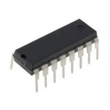
TEA1101P
Availability: In Stock
Add to Compare
CONTROL FOR BATT.CHARGER,PHILIPS
| Documentation | |
Datasheet  |
|
Product Specification
| Feature | Battery Charger |
|
4.1 Battery Charger
|
Write a review
Your Name:Your Review: Note: HTML is not translated!
Rating: Bad Good
Enter the code in the box below:
Cambodia Electronic Source © 2024


