Your shopping cart is empty!
Categories
- 5W Resistor (6)
- Arduino Development (66)
- Audio (8)
- Batteries (17)
- Cable & Wire (36)
- Capacitors (41)
- Charger (7)
- CNC Machine (4)
- Connector (26)
- Connector (3)
- Connector & Sockets (3)
- Crystals / Oscillators (9)
- DCA Professional Power Tools (0)
- Development Tools/ Programmers (10)
- Digital Oscilloscope (0)
- Display (64)
- Domino (5)
- Driller (16)
- ECOSPARKS PRODUCTS (0)
- Electrical Products (1)
- Ferrit (1)
- GPS Module (5)
- GSM Module (8)
- Headers (15)
- Heat shrinkable tubing (7)
- IC-Driver (17)
- IC-Microcontroller (31)
- IC-OpAm (13)
- IC-Timer (5)
- Inductors SMD (0)
- Inductors/Coils/Chokes (16)
- Integrated Circuits ( ICs ) (1)
- Max Family (7)
- Micro SD (7)
- Module Bluetooth/ Bluetooth (5)
- Module Relays (6)
- MosFet & Fet (15)
- Motor Pump (3)
- Optical Sensor (11)
- Optocouplers (3)
- Other Products (1)
- Over Voltage / Current (11)
- PCB (16)
- Potentiometers / Variable Resist (16)
- Power Supply (15)
- Projects Box (1)
- Raspberry Pi (29)
- Regulators (20)
- Relays (11)
- RePair Battery LapTop (2)
- Resistor-Network (3)
- Resistors (52)
- RF IC, Module (13)
- ROBOTIC (55)
- Semiconductors (0)
- Sensors / Transducer (81)
- Service and Repare (0)
- Smart Home (2)
- Socket-IC (10)
- Solar Panel (4)
- Solder (8)
- Soldering Tool (28)
- Specialized Function IC (10)
- surface mount (SMD) (35)
- Switches, Key Pad (25)
- Terminal block (11)
- Test & Measurement (21)
- Testboard (6)
- Tools & Supplies (56)
- Transistor (32)
- Triac (3)
- USB Connector (9)
- USB to Serial (12)
- WiFi Module (14)
- Wire Termial (15)
- Diodes (20)
- IC-Logic Family (29)

Module 8 Relay

Product Code: Module Relay
Availability: In Stock
Availability: In Stock
Price: USD 5.00
Qty:
- OR -
Add to Wish List
Add to Compare
Add to Compare

DESCRIPTION
The relay module has eight independent 5V logic compatible relays that control 125/250VAC@10A or up to 15VDC@10A each.
PACKAGE INCLUDES:
- Relay Module 5V x 8 Relay w/ Opto-isolation
KEY FEATURES OF RELAY MODULE 5V X 8 RELAY W/ OPTO-ISOLATION:
- 8 independently controlled relays
- Switch AC up to 125/250VAC @ 10A
- Switch DC up to 15VDC @ 10A
- Normally Open (NO) and Normally Closed (NC) contacts
- LED indicators when relays are energized
- Can operate with opto-isolation or without it
- 5V logic compatible
Relay modules are handy for controlling external loads. Unlike transistors used for switching, relays use metallic switch contacts which avoids the power loss and heating inherent in transistor switching circuits. They are also nicely contained little modules that are simple to hook-up and are especially useful for switching AC. The main downside to relays is that being an electro-mechanical device, like any mechanical switch relays are more prone to wear and tear over prolonged use.
Module Control
These relays are fully 5V logic compatible. The inputs have a relay driver transistor and opto-isolator built-in which means the device needs < 5 mA on the logic control pin to drive it. If you have an MCU like an Arduino, you can drive the relays using any of the digital output pins.
The relays are activated with a logic LOW signal. There is a red LED that is lit when the control pin for that relay is driven low to activate the relay. When the relay is activated an audible click will be heard. A logic HIGH or no input deactivates the relay and the LED will go off.
Opto-Isolation
The board includes opto-isolators on the logic inputs.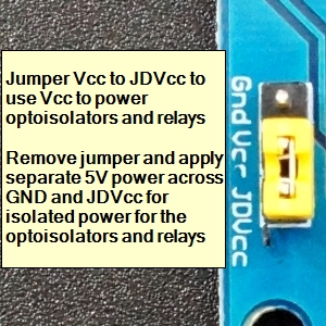
Opto-isolators provide complete electrical isolation between the logic control input and the relay power as an added layer of protection in case of a lighting strike or some other kind of major failure on the AC load of the relay.
As-shipped, the module has a jumper between header pins JD-VCC and VCC (relay power is jumpered to logic power). This bypasses the opto-isolation circuit as it ties the relay power to the logic power, but it makes the device easier to use since just one power supply needs to be connected to the module.
If it is desired to enable opto-isolation, remove the jumper and provide a separate 5V power supply voltage to the JD-VCC and GND pins on that connector.
Module Power
The module requires 5V power and Ground to operate. If opto-isolation is used, it will require two different 5V power sources.
The ground must be common with the MCU. Flyback diodes are included on the module in parallel with the relay coils to safely shunt current when the relay coil is de-energized.
When a relay is energized, the module draws about 70mA from the Vcc pin. With all eight relays energized, the draw is about 600mA.
Relay Operation
The output of the relay is rated to switch up to 30VDC at 10A per the relay markings (see our notes below) or up to 125/250VAC at up to 10A.
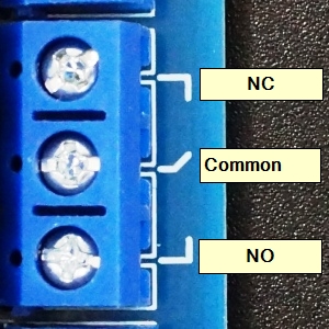
The output is SPDT type with both a NO (Normally Open) terminal and a NC (Normally Closed) terminal relative to the center unmarked common (COM) terminal. A logic HIGH energizes the relay, so the NO–COM contact is closed and the NC-COM contact is open. A logic LOW de-energizes the relay and the NO-COM contact is open and the NC-COM contact is closed.
Module Connections
1 x 10 Header
- GND = Connect to ground of the 5V power supply
- IN1 = Relay control input 1. Logic LOW level energizes relay 1
- IN2 = Relay control input 2. Logic LOW level energizes relay 2
- IN3 = Relay control input 3. Logic LOW level energizes relay 3
- IN4 = Relay control input 4. Logic LOW level energizes relay 4
- IN5 = Relay control input 5. Logic LOW level energizes relay 5
- IN6 = Relay control input 6. Logic LOW level energizes relay 6
- IN7 = Relay control input 7. Logic LOW level energizes relay 7
- IN8 = Relay control input 8. Logic LOW level energizes relay 8
- VCC = Connect to 5V power supply
Relay Contacts
- NC = Normally Closed side of the relay
- Center Terminal = Common terminal usually connects to the load power source
- NO = Normally Open side of the relay
1×3 Header
- JD-VCC = Opto-isolator power input. Jumper to Vcc to run off same power supply as the logic (default mode). If opto-isolation is desired, remove jumper and apply a separate 5V supply to this pin.
- VCC = Same as Vcc on the 1×10 header
- GND = Same as GND on the 1×10 header. Can be used to connect ground of separate 5V power supply (if used)
OUR EVALUATION RESULTS:
These are nice inexpensive modules that will work for many applications.
We did find the DC rating of the relay to be too aggressive. With DC voltages above about 15V, the contacts can become a little sticky and not release when commanded to do so. If using it to switch DC voltages, it is recommended to limit the voltage to 15V or lower.
With AC, the relays performed very well in our testing. To test the upper limit we used it to switch a 1500W heater which drew about 12.5A which is above their spec and the relay handled it without any problems.
Write a review
Your Name:Your Review: Note: HTML is not translated!
Rating: Bad Good
Enter the code in the box below:
Latest


Powered By OpenCart
Cambodia Electronic Source © 2024
Cambodia Electronic Source © 2024